In chemical industries most of the reaction that takes place are exothermic reactions. In simple words exothermic processes are the reactions in which heat is liberated. Generally in most of the chemical industries, the heat liberated during a process is utilized in pre-heating of the reactants or in some other processes involving high temperature requirements. Therefore one question arises what if the heat liberated in a process is more than the required heat of pre-heating of reactants or because of some reasons we are not able to utilizing it in a efficient way, so for this kind of situation we have designed a process of utilizing the heat in the generation of electricity. Our project aim is to design and simulate a waste heat management flowsheet and to increase the efficiency of plant by using waste heat and to make optimum use of fuel. We are using ASPEN PLUS software to design the flowsheet and simulate it under given conditions.
In order to study about various process taking place in industries , we learned about the three types of
Flow Diagram - Block Flow Diagram, Process Flow Diagram and Piping & Instrumentation. The study of these flow diagrams
helps in dertermining the process and the direction of process taking place in the industries. Along with the flow Diagram ,
Componens in the Flow Diagram also matters lot in determing the energy transffer in the process.
Following are the main
components of the Flow Diagram:
In order to developed our own process and its Flow Diagram , we went across few previously developed processes like:
Thus after developing thorough knowledge about the unit processes and their Flow Diagram, we started developing our own processes and their flow Diagram using ASPEN Plus to determine the efficiencies of the process. We have developed three different Flow sheets for three different process like Distillation , CO2 gas Capture plant and Electricity producing Plant.
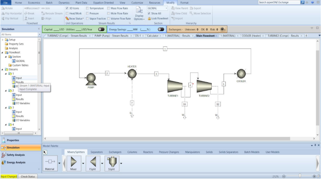
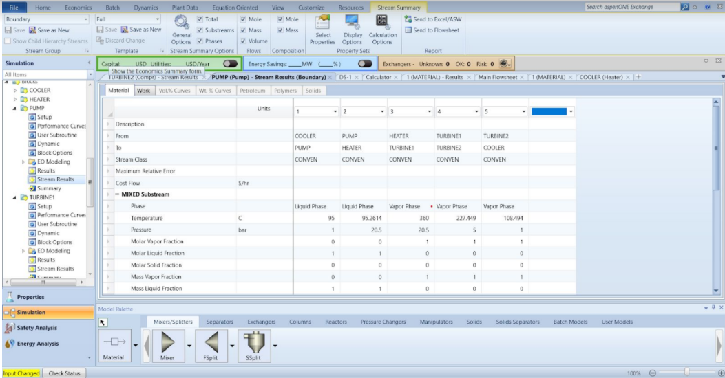
It is clear from the Flow diagram that water is used as feed. After going through the pump and with raise in pressure energy, water enters the heat exchanger and gets converted in steam. This steam is allowed to flow through the blades of the turbine and hence energy is produced through the rotation of the turbine blades. Here we have used two turbines to increase the efficiency of the plant. Thus after going through turbines steam is passes through condensor and again gets converted to water which is passed to the pump. The heat produced in the condensor can be used to rise the temperature of water in heat exchanger.