Pumps in the chemical industry are very crucial to supply energy for transporting or compressing fluids. Working on the basic principle of conservation of energy, pumps serve in a wide range of applications such as aeration, in the car industry for water-cooling and fuel injection, in the energy industry for pumping oil or natural gas or for operating cooling towers. Pumps are also used in the medical industry in artificial replacement of body parts such as artificial heart and penile prosthesis. Centrifugal pumps are the most widely used and hence play an important role in industrial operations. Along with pumps, components like valves help us to control the process variable of flow rate. With the growing demands for digitalisation and advanced process control, the automated detection of flow parameters is yet another milestone to be achieved across all industries. This project aims at developing a electrically powered Centrifugal Pump which can varies its flow rate depending upon the requirement. It is an amalgamation of Fluid Mechanics and process control.
Overview of Centrifugal Pump
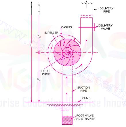
Pumps are hydraulic machine which develops hydraulic energy (Pressure Energy) by converting mechanical energy. In centrifugal Pumps , the mechanical energy is converted to hydraulic energy (Pressure Energy) by means of centrifugal force acting on the fluid. In a sense, centrifugal pumps are reverse of inward radial flow reaction turbine which implies that the flow in centrifugal pump is in radial outward direction. Centrifugal pump works on the principle of Forced vortex flow which means that when a certain mass of liquid is rotated through external torque, the rise in the pressure head of the liquid takes place. Due to this pressure head , liquid can be lifted to high level.
There are four main parts of the centrifugal pump:
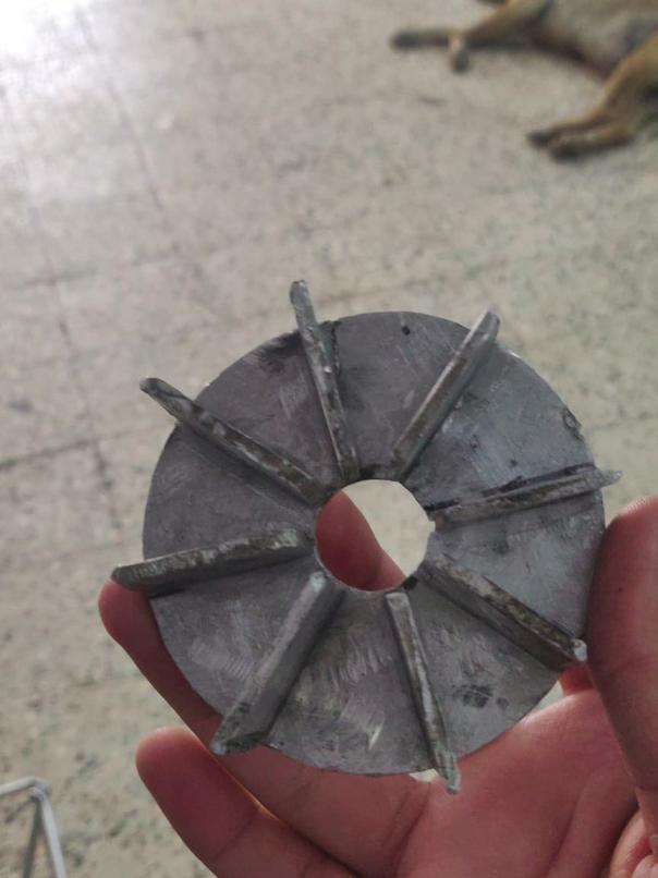
The main component of the pump is Impeller. It is the rotating component of the centrifugal pump and it contains series of vanes. This impeller is mounted on a shaft which is then connected to the shaft of the motor. Casing is an air tight passage surrounding the impeller of the pump. Casing of the pump can be of three types volute casing , vortex casing and casing with guide blades. A pipe whose one end is connected to the inlet of the pump and other in the water sump is known as suction pipe whereas the pipe whose one end is connected to the outlet of the pump and other delivers liquid to required level is known as Delivery Pipe.
Design parameters taken into consideration:
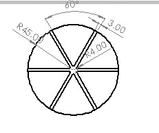
Considering these design parameters and various calculations about the efficiency, power output and work done by the pump, we have designed various impellers and the following two designs of the impeller were giving suitable outcomes.
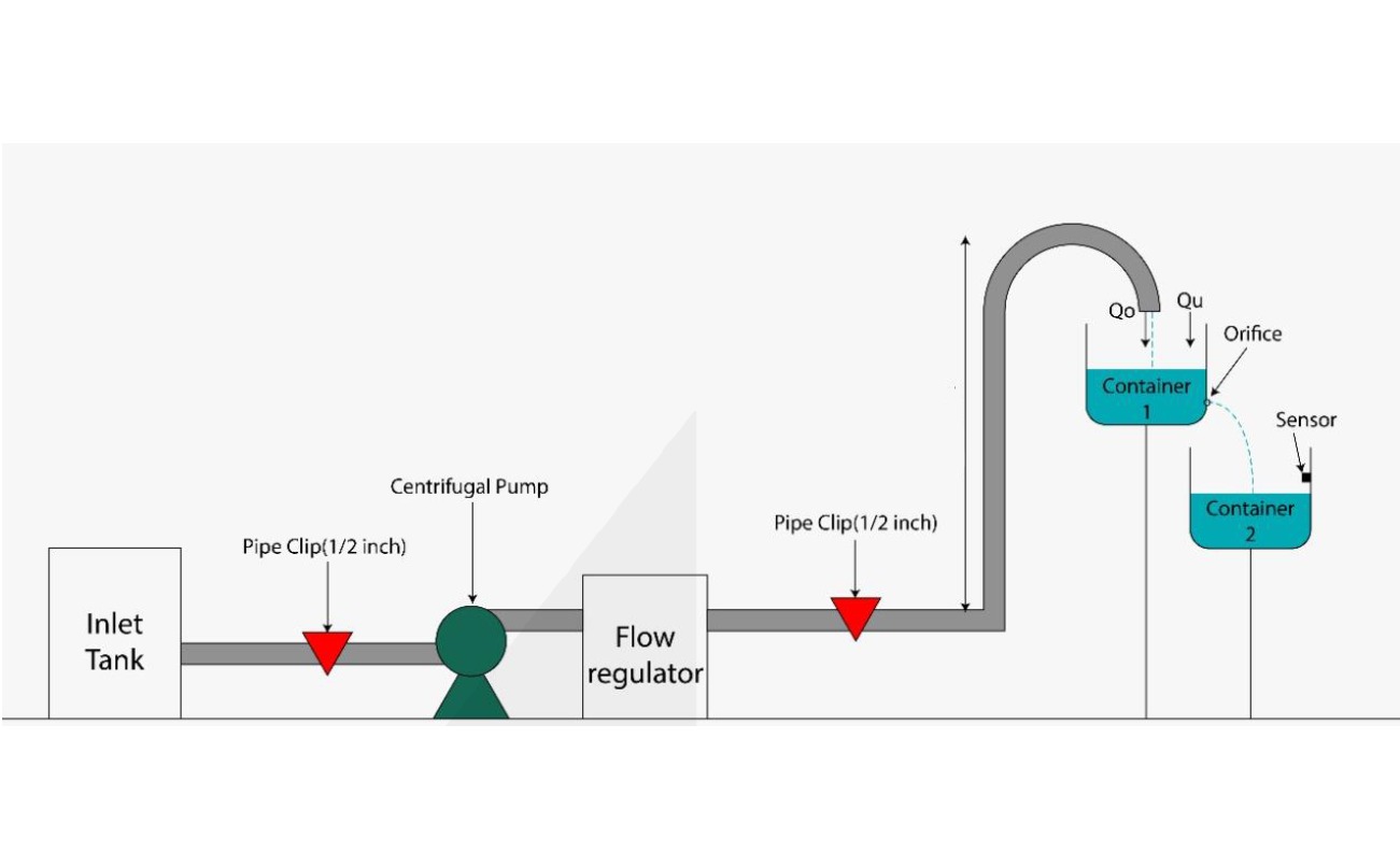
Final Model
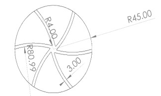
After working on various calculations and considering all the important parameters, the final model of the centrifugal pump was manufactured. The impeller diameter was of 90 mm having 6 blades each 3 mm thick and 35 mm in height. The base motor of Chinese motor having nearly 18000 rpm was Selected and impeller was coupled with the motors shaft. He casing of the centrifugal pump was volute casing of 130 mm in diameter and 45 mm height. The deliver pipe was around 3.5 to 4 m in length and hence liquid was pushed to that height with outlet flowrate of nearly 5 litres/min. Among various sensors, in order to measure the flow rate of unknown liquid we have used water Flow sensor which directly gives the value corresponding to the Flow Rate. In order to control the Flow Rate we have developed 2 technologies, one was with the help of the mechanical valve by which we can manually set the value of the desired Flow rate and the other was with the use of motor driver citron. With the help of the Citron we can control the rpm of the motor as per the desired output flow rate.