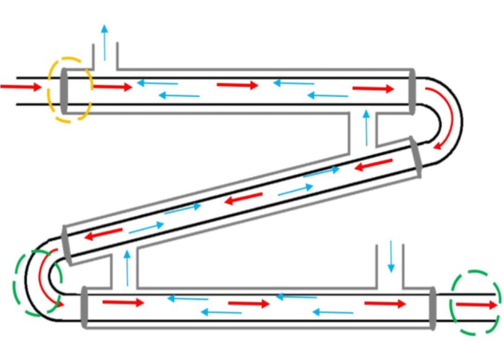
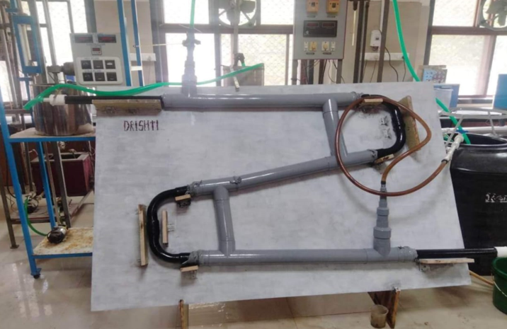
A double-pipe heat exchanger is a widely used equipment for transferring heat from one fluid to another in the industry. It consists of two concentrically arranged pipes or tubes, with one fluid flowing inside the inner pipe and the other in the annular region between the pipes. Special end fittings are used to get the fluids into and out of their respective flow channels and keep them from leaking into the atmosphere. The operation of a DPHE is enhanced by using auxiliary equipment like valves, pumps, meters, switches, and controllers.Operations are carried out per the requirements taking into consideration safety regulations.
This project aims to design and develop the best possible Heat Exchanger with the minimal expenditure.The project involved manufacturing and testing of a Double pipe Heat Exchanger at a laboratory scale.The final model was prepared in accor- dance with the calculations and design developed throughout the project duration.
Overview
Heat exchangers are devices which are used mainly to transfer heat from one fluid to another fluid. These media may be a gas, liquid, or a combination of both. The media may be separated by a solid wall to prevent mixing or may be in direct contact. Most exchangers consist of coiled pipes (which is generally made up material with high thermal conductivity) passing through a chamber which is generally whose outer coating is generally made up of insulating material to prevent heat loss.
It is a device that allows heat from one liquid (liquid or gas) to be transferred to another liquid or gas without the two-liquids mixing or coming into direct contact. They are used for cooling components featuring water to air, liquid-cooled, closed- loop systems.

Parameters taken into consideration
Construction
Depending on the pipe configuration, double-pipe heat ex- changers are classified into straight coiled pipes and helical coiled pipes . Helical coiled double-pipe heat exchangers are considered the most applicable type of heat exchangers in various industries including cooling applications because of their high performance, high heat transfer rate, and compact volume.In a double-pipe heat exchanger the inner pipe is made of a conductive metal and is thin.
Components
Final Design
The hotter flow is traversing the inner tube, while the outer shell contains the cold flow (note that this is not always the case). The double pipe heat exchanger works via conduction, where the heat from one flow is transferred through the inner pipe wall, which is made of a conductive material such as steel or aluminum.On the basis above performed calculations, we chose the most efficient and economical material design as follows.The inner pipe material is made up Mild Steel (MS ) which has a thermal conductivity of 45 W/m K.It was chosen considering economic as well as the efficiency factors.The diameter of MS pipe is 1.5 inch 40 Schedule Number and the heat transfer length is 2.74m through which the hot fluid flows.The outer pipe is made of PVC of grade 3 Schedule No. 40 with 2.5 inch diameter providing an insulation to the atmosphere due to its Thermal Conductivity of just 0.18 W/m K.The cold fluid flowing in the Annular region transfers heat to the outer pipe which gets minimised due to PVC.
Two 90 degree Galvanised Iron (G.I.) elbows of are utilised for creating a structure similar to U-bend Hairpins.They are threaded on both ends for proper fittings with the inner pipe of 1.5 inches.Couplings are important for connecting two two elbows to create a Hairpin and four such to connect the elbows with the inner pipe for smooth flow,These fittings have sockets at both ends which are fastened with the pipes.A rubber cork of 2.5 inch was utilised as a stopper at both ends of the three pipes for blocking the flow of the cold fluid in annular region. A concentric hole of 1.5 inch is created in each of Six corks for allowing the inner MS pipe to pass through it.Tee-Joints of PVC of 2.5 inch dia were used to connect two parallel outer pipes fot the smooth flow of cold flow.It is assembled in such a way that least amount of dead zone as well as least pressure drop is created.
Reducers of various fittings were required for connecting the Pipes of the DPHE with the reservoirs and the pump.PVC reducers were broadly used because of economic constraints.M-seal,Plumbing Glue and Silicon tapes were utilised for keeping all the leaks in check. An inclined stand was created for the whole Heat Exchanger to rest upon. It is built of waterproof Plywood along with supports attached to support the setup.

Final Results
The Average values of LMTD, Heat Flow rate and Overall Heat transfer Coeffi- cient for Hot fluid is found to be
LMTD = 24.428 °C
Heat Flow Rate = 1572.975 W,
Overall Heat Transfer Coefficient = 133.87 W/m2 °C.
The rate of heat transfer is largely affected by the flow rate of both the fluids,dead zones,insulation provided and the length of the pipes.
Inferences Of Final Design
1 - Rubber corks attached to the ends of PVC pipes produce a dampened zone where fluid remains stagnant; this increases the fluid’s retention time with the metal pipe, forcing it to absorb more energy than the energy released by hot fluid. Consequently, this error is reflected in the outlet temperatures of both fluids.
2 - At the bends of metal pipes and areas where they are exposed to the atmo- sphere, additional heat loss occurs, increasing the temperature difference between the inlet and outlet of a hot fluid. PVC pipe has a Thermal Conductivity of 0.25W/mK . This amount, though mi- nor, contributes for a significant energy loss from the PVC pipe to the environment due to the larger length of pipe; hence, the estimated values for the net effective heat transfer to the cold fluid vary from the theoretical values.