Heat transfer is having importance in many different areas, for example, solar application, waste heat recovery, electronic cooling in computer, and all other electronic components which generate heat. Generation of heat takes place in many applications and this heat must be transferred or removed from the immediate environment and ejected in some suitable heat sink. Therefore, it is necessary to find more efficient method of removing heat from source to sink. Heat pipe is one of such promising technology which can be used to transfer large amount of energy over a small temperature gradient because of large latent heat transfer associated with the phase change processes. Their simple design, cost effectiveness, high efficiency, good compactness, reliability and durability have made them very attractive for many industrial applications like waste heat recovery, heating ventilation and air conditioning, electronic cooling, human body temperature control, cooling of gas turbine rotor blades, solar energy etc. It is used to improve the thermal performance of heat exchanger and with increasing energy saving application with commercial use.
Overview of Heat Pipe
The best-known capillary driven two phase system is the” HEAT PIPE”. Heat pipe is defined as a
highly effective passive device which is used to transmit heat at high rates over considerable
large distance with very small temperature drops with simple construction, easy control and no external pumping power.
Heat pipe has three main basic components:
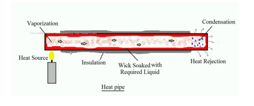
A typical heat pipe consists of a sealed tube or pipe (cylindrical shape is not necessary, it can be of any shapes as per the application) made of a material that is compatible with the working fluid. Such examples are aluminium is used as a material when ammonia is used as a working fluid or copper is used as a material when water is used as a working fluid. This container is divided in three parts along the length.
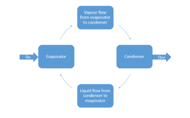
In evaporator section (heat source), heat is supplied to the working medium so it will vaporise. Adiabatic section is highly insulated section to minimise the heat loss to or from the surrounding. In condenser section (heat sink), heat is rejected to the heat sink by the working medium so it will be converted into liquid. It is not necessary to have only one source or sink; it may have more than one source and sink as per the requirement of the application. The heat pipe is partially filled with a working fluid and then sealed. Once the filling is done, it is sealed. Mass of the working fluid is chosen in such a way that heat pipe contains both vapour and liquid over the operating temperature range. The wick is selected as per the working fluid and the application.
Design considerations and Factors affecting heat pipe performance:
Operating Parameters:
Numerical Model
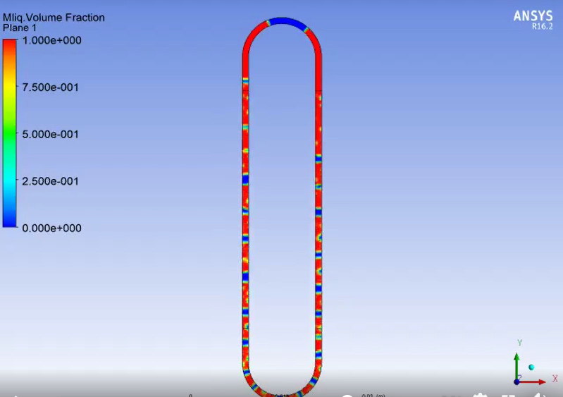
The computational analysis was carried on Ansys 16. the geometry of Heat Pipe was developed according to its application in Design Modeller and mesh was generated. Near wall mesh was kept highly refined compared to the other mesh as to capture the minute changes occurring near the wall. The computational simulation is carried out to study two phase flow and heat transfer phenomena in the Heat Pipe by using FLUENT 16. The volume of fluid method is used to simulate the multiphase flow. Depending upon the use of Heat Pipe in some cases the body force term was included and, in some cases, it was neglected. The Body force term was considered by activating the acceleration due to gravity. A transient simulation with a variable time step which varies in the range of 0.0001 to 0.0005 sec is carried out to model the dynamic behaviour of the multiphase flow. The time step is selected based on the Courant number, is the ratio of the time step to time require for fluid to move across the cell. The numerical simulation is considered to be converged when the residuals for mass and velocity components are reduced to 10-6.
Result
Various parameters were considered during the solution of numerical model and from the solution results were plotted regarding temperature contour and volume fraction of Steam or liquid.